
Case study · Subsea engineering
Engineering development of a subsea jetting trencher
Our principal engineer acted as Mechanical Technical Lead on a subsea jetting vehicle for cable trenching, taking the mechanical engineering from an established concept through detailed design, manufacture, commissioning and Factory Acceptance Testing.
- Mechanical engineering taken from established concept to client-witnessed factory acceptance
- FAT
- High-capacity jetting pumps integrated into the vehicle
- 3
- Load regimes verified: vessel deployment, subsea operation and towing
- 3
- Functional Design Specification written to define the control system
- FDS
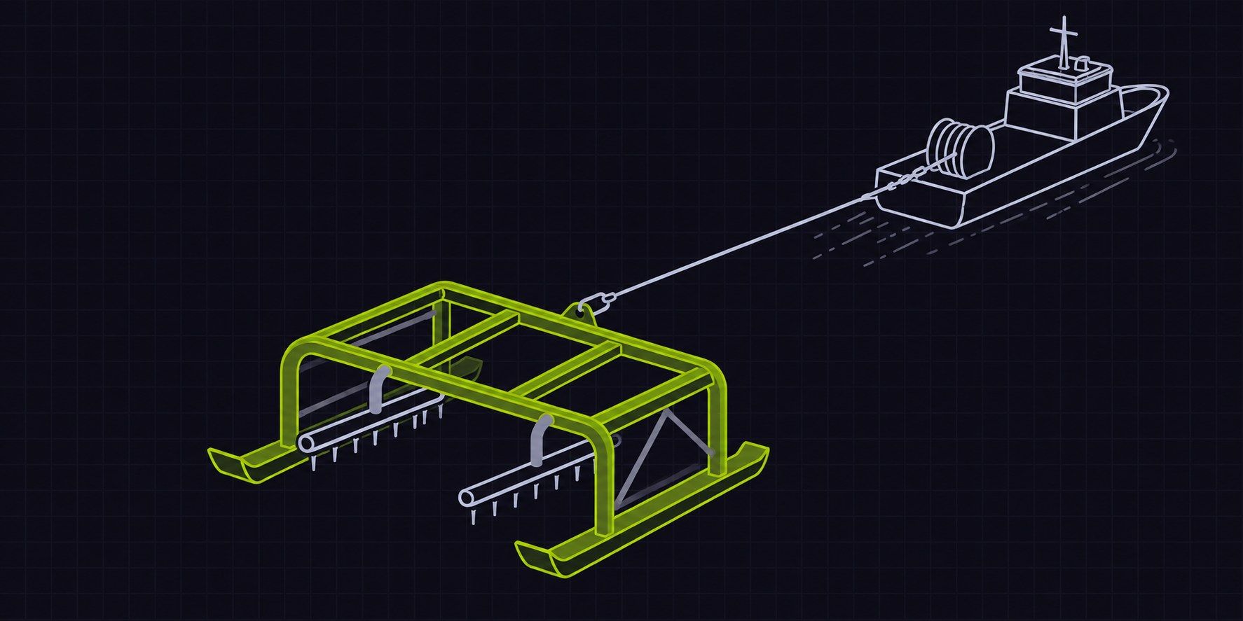
The system
A subsea jetting vehicle for underwater trenching. It combines high-capacity water jetting, hydraulically actuated jetting equipment, the vehicle structure and integrated controls to excavate a trench for subsea cable burial.
The challenge
Multiple mechanical, hydraulic and jetting systems had to work together on one vehicle. The engineering had to establish vehicle performance requirements, design the deployment mechanisms for the jetting equipment and integrate the high-capacity jetting system.
The structure had to be verified for vessel handling and deployment, subsea operation and towing. Delivery depended on close coordination between mechanical, structural, hydraulic, electrical and software engineering.
| Sector | Subsea engineering, offshore energy |
|---|---|
| Engagement | Mechanical Technical Lead within the delivery team |
| Authority | Final technical authority for mechanical design and calculations |
| Disciplines | Mechanical, structural, hydraulic, electrical, software |
| Phases | Performance, concept, detailed design, manufacture, commissioning, FAT |
Programme
From conceptto factory acceptance
- Phase 01
Performance
Vehicle-level performance requirements established.
- Phase 02
Subsystem concepts
Concepts developed for the jetting deployment and key subsystems.
- Phase 03
Detailed design
Mechanical design, global structural analysis and verification.
- Phase 04
Drawing release
Design released for manufacture.
- Phase 05
Commissioning
System integration and functional testing.
- Phase 06
FAT
Client-witnessed Factory Acceptance Testing.
Our approach
What we did
Technical leadership
Our principal engineer acted as Mechanical Technical Lead, holding final technical authority for mechanical design and engineering calculations.
He directed the mechanical engineering team, coordinated technical deliverables, chaired client design meetings and managed the engineering interfaces with the other disciplines, taking the programme from vehicle-level performance assessment and subsystem concepts through to detailed design and verification.
Mechanical and structural engineering
He led the design and analysis of key mechanical subsystems, including the hydraulically actuated deployment mechanisms for the jetting equipment.
Global structural analysis assessed the vehicle across vessel deployment, subsea operation and towing, establishing its structural response and verifying the primary structure and mechanical interfaces.
Jetting system design and integration
Three high-capacity water pumps supply the jetting equipment through distribution manifolds and pipework. He contributed to the mechanical design and integration of the system, including pipework arrangements, equipment interfaces and routing.
The work also coordinated hydraulic power requirements, actuator interfaces and mechanical integration with the vehicle structure.
Functional design and controls
He wrote the Functional Design Specification, defining equipment functions, operational requirements and control interfaces.
Working with the hydraulic, electrical and software engineers, he established HPU requirements, hydraulic circuit interfaces, service routing and operating sequences, and developed operator interface concepts for the vehicle control system.
Manufacture, commissioning and FAT
After design and drawing release, he provided continued technical support through manufacture and commissioning.
That support carried through system integration and functional testing to client-witnessed Factory Acceptance Testing.
Outcomes
Our contributionfrom concept to FAT
- Mechanical engineering taken from an established concept through detailed design to Factory Acceptance Testing, under a single mechanical technical authority.
- Global structural verification completed across deployment, subsea and towing conditions, with the jetting deployment arrangements designed and verified.
- Functional Design Specification produced and the jetting system integrated, supporting the control system through manufacture, commissioning and FAT.
Capability demonstrated
AuraTech provided the Mechanical Technical Lead within a wider multidisciplinary delivery team. Project details have been generalised to respect client confidentiality.
Start a project